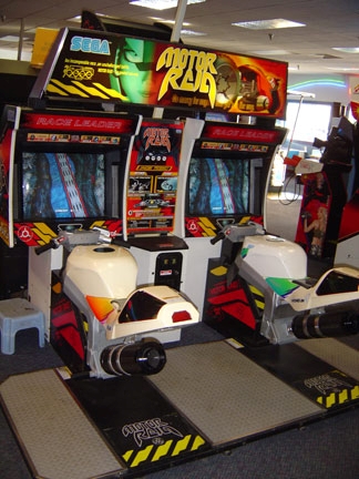
It’s been a long time since anyone has worked on the RC Car project here in the Workshop and since I’m new to this project I figured now is a great time to begin simplifying and streamlining the wiring. The way everything was wired previously was great for prototyping but it left something to be desired for a more polished product. A lot of the wiring had gotten messed up from moving the bikes and just leaving the project unused for so long, so I grabbed a multimeter and began the work by checking all the connections. Previously a breadboard was used to send power to the bikes and also serve as a hub point to read the data from. This created a mess of wires that made it difficult to see how things connect and so I soldered up all the power lines and ground lines and added on a male pin. Now they can be directly connected to the 5v and GND pins on the Arduino itself. I then added male pins to each of the three signal wires so that they too could be plugged directly into the Arduino. With this new setup, I could eliminate the breadboard which cleaned up things nicely. Now that the connections were simplified I verified that everything was working and turned my attention to the RC car itself. When I began working on the car nothing seemed to be responsive. So, I decided to dissemble the system and redo it, following the same guidelines used previously, which fixed the issues. Now both Arduinos are communicating correctly and everything seems to be working except for the throttle which is glitchy at best. Once the receiver side is fully functional I’ll streamline the wiring and clean it up. Things on the to-do list for this project now are:
- Fix Throttle response
- Clean wiring on receiver side
- Add buttons to enable reverse mode
- Reimplement the FPV system
Once all these are done I’ll be designing a PCB that will condense everything and make the project more professional. Below you’ll find the current versions of the code being used on the project.
-Andrew