
Maker Faire Orlando 2017 - Part 2
Ever since attending the Mini-Maker Faire in Miami this year I have been thoroughly excited for Orlando’s event. There were so many cool projects and people this year and it was awesome being able to see everything that was on display. There were three things that really stood out as I browsed the Faire. Outside of the Workshop I am the president of a robotics club at a local university, and so it should come as no surprise that my favorite things to check out were all the amazing robotics being shown. From FTC builds to Battle Bots, Astro droids to Repair Droids there were all amazing. Two robots in particular that stood out to me were the Renaissance Robotics FTC build and steampunk R2 Droid.

Maker Faire Orlando 2017 - Part 1

Hybridized Garrett Boca Bearings Turbine - Part 3
I have been extremely busy in the workshop recently and trying to make more progress on the turbine has slowed down a bit since most of the turbine unit is disassembled. The last part of disassembly of the turbine deals mainly with the CHRA and removing the journal bearings completely. Tools necessary for the task:
1. Small snap ring pliers
2. Patience
1. Small snap ring pliers
2. Patience
Hybridized Garrett Boca Bearings Turbine - Part 2
The initial teardown of the turbine started with the larger and more basic components of the unit such as the housings, drain pipe, and other various components. It was then that I was left with just the CHRA and its internal components. So now I began the teardown of the internal parts of the turbo.
Necessary tools:
Necessary tools:
Hybridized Garrett Boca Bearings Turbine - Part 1
In the perfect physical world, there would be no gravity or no coefficient of friction. As we all know that is completely unreal. With the idea of gravity in mind, it would be in everyone’s best interest to try and reduce the coefficient of friction as much as possible. Reducing the coefficient of friction in general helps improve efficiency and performance of almost anything moving (i.e.: bearings, lubrication). Now you are probably asking yourself why should someone or anyone know this vague information. The answer is that this same basic principle applies to your daily activities whether you notice it or not. The easiest example of this is the car you use to commute to and from point A&B. To demonstrate this theory of reduction the coefficient of friction, I will be inserting new ball bearings into a 30-year-old turbo charger that is used on gasoline and diesel engines.
Boca Bearings Workshop Weekly Update 5
The first new project I’ll be talking after Maker Faire Orlando is a sorting machine. The goal will be to sort skittles (or any uniformly shaped and colored candy) into separate cups. The project is heavily based on the fantastic work done by Willem Pennings on his blog which you can find here: https://willemm.nl/mm-skittles-sorting-machine/. There have been other sorting machines similar to this, but I think Willem’s looks the best and so that is the design I’ll be drawing from the most. Over the last week I’ve put together a parts list and begun to CAD the mechanical aspects of the project. Below you’ll find a link to my list of components and the cost so if you would also like to make one you have a good starting point. Once I finish modeling the system I’ll make the files available so that anyone can reproduce the project as well.
Boca Bearings Workshop Weekly Update 4
The last few weeks I have been busy refurnishing the bike for the RC car project as well as designing 2 versions of the chassis for the car itself.


3D Scanner Project Update 1
Our 3D scanner has always been a great machine, however, the difficulties in setup make it somewhat of a pain to use. To improve the capabilities, reliability, and ease of use of our scanner I looked to improve upon it somehow. I thought upgrading the sensor being used to a Kinect 2 would be an improvement but as it turns out the technology in the Kinect 2 changed and is no longer a viable solution to DIY scanning. After some investigating I found that the best (and only solution, if I’m honest) is to use a Structure Sensor from https://structure.io/. Luckily, we happened to already have one not in use so after validating it would work with our software I loaded up SolidWorks and began designing a new bracket to hold it in place. What I ended up with is this:
Boca Bearings Workshop Weekly Update 3
RC Airboat
I finally “finished” the airboat. I finished making the last of the rudder design so with that part being finished I decided to do the boats first test run. Prior to me making the different designs and modifications to the hull of the boat. I never actually put the boat or the hull of it in the water for a “sink or float” test. To help with the buoyancy of the hull I added an epoxy resin to the bottom of the hull, but again I still never tested it out.
RC Car Project - Update 3
With
most of the body completed it was now time to do some fine tuning to the
steering and throttle. Steering adjustments were relatively straight forward, I
wanted there to be a dead zone where the car could go straight even with the
bike not being in perfect center. In order to achieve this I put in some simple
logic to the code:
Boca Bearings Workshop Weekly Update 2
Pi-Zero Drone:
This week I made the silicate elastomer mixture of cornstarch and silicon I* to make tires for the drone. I didn't expect the mixing of the ingredients to be as messy as it was, but the finished product turned out to be a great success. The drone now has good traction on slippery concrete. The only down side to the new tires is that the shape of one of them is a tad lumpy which occasionally alters the direction of the bot. I should be able to fix that by shaving off some material.
Boca Bearings Workshop Weekly Update 1
Weather Vane
I finally have the rpm counter/wind speed monitor working for the weather vane. The next step in this process is to finish building a sturdier base for the weather vane, to enable it to be properly planted. Once I get the structure of the weather vane down, I will then test it outside with the electronics to test two things:
RC Car Project - Update 2
Whew! Another long time since an update on the RC Car project!
There have been some major developments on the project since last time and I’ll go through them here.
After the last update, I did design a PCB to condense the project into a neater form factor, however there were several issues with the design and ultimately the board was nonfunctional. After spending a few days attempting to get the board working correctly I made the decision to put that on hold and get the car working again (it was dissembled for parts). This was supposed to be a simple task considering I had done it once but after several days of work I was left unable to make the radio modules communicate with each other. It was at this point I decided to move the system to a new platform.
Zerobot Project - Update 3
This week the new parts came in. I tested the operation using brand new Zeros and cameras. Found a defective motor controller on Zero 2.0. After replacing it, the wheel no longer rotated prior to booting up. I have successfully created an SD image file to burn onto any new SD card that operates a new Zero correctly. The only change in the file is correcting the IP address to the one of the new Zero.
Zero 1.0 and 2.0 are both fully functional. For the tires on 2.0, I was having issues printing the NinjaFlex so they were printed with PLA. This created traction issues and I attempted in overcoming those by wrapping the wheel in electrical tape.
Zero 1.0 and 2.0 are both fully functional. For the tires on 2.0, I was having issues printing the NinjaFlex so they were printed with PLA. This created traction issues and I attempted in overcoming those by wrapping the wheel in electrical tape.
Zerobot Project - Update 2
This week I have completed Zerobot version 2.0 and have gotten 1.0 working to spec. As always, Issues have arisen. Version 1.0 was working perfectly on Friday, but on Monday, the left wheel would not rotate counterclockwise. I installed a new motor with no change in result. Version 2.0 operated with the same SD card as 1.0. The motors would operate on port :3000 but I had no video stream. The video stream would operate on port :9000 but I had no controls. Another issue on version 2.0 was the left wheel would rotate when power was turned on until the Zero booted up. Once the Zero booted up, the wheel would stop and operate correctly.
Zeorbot Project - Update 1
This week, I have received all of the parts required to complete the Zerobot. I completed the assembly of the electronics and mechanics of the bot. Since I used a different battery pack, I made some additional modifications. In the original writeup by Max.K, the battery and power charging chip were separated inside the bot. In my construction, I kept the components together and cut out a port in the rear of the bot to allow for charging and power supply to the Zero. I will likely hardwire the Zero in the future but this allows me to turn it on and off by unplugging the battery while the bot is sealed. I improved the mounting of components to the PLA chassis. The motor controller was screwed in to one of the ribs. One issue this week was the fitment of the camera. The ones I ordered have a chip in the wire which hinders flexibility. Luckily, the maximum bend rested the camera in place without needing permanent attachment. The motors had dual directional output drives that were interfering with the other components. I removed the inner drive by cutting them off.
The Zero and motor controller have been soldered and wired along with the motors themselves. I changed the GIPO ports used for wiring for cleanliness. This will require changes in the coding provided, that I will look to complete by next week. As of now, the Zero is powered by the USB output on the power bank, and sends that power to the motor controller via 5V output and ground.
The Zero and motor controller have been soldered and wired along with the motors themselves. I changed the GIPO ports used for wiring for cleanliness. This will require changes in the coding provided, that I will look to complete by next week. As of now, the Zero is powered by the USB output on the power bank, and sends that power to the motor controller via 5V output and ground.
The World's Largest 3D Printed Fidget Spinner

3D Printer Filament Stand Project
Today I built a filament stand for our 3D printers. I wanted to hold 24 rolls on the back and will be adding posts for the most common ones up front.
Built from
This was a simple design but was constructed without the use of power cutting tools. ½” holes were drilled evenly spaced and rods that were cut into thirds were pressed in via hammer.
Built from
- 3 – 2x4x12
- 10 – ½” dowles
- Construction wood screws
- Cost – 50$
This was a simple design but was constructed without the use of power cutting tools. ½” holes were drilled evenly spaced and rods that were cut into thirds were pressed in via hammer.
Zerobot Project Introduction

I was assigned to create a step by step instruction manual for others at the company and future interns to build a project that uses many of the tools available at Boca Bearings. The Zerobot was selected as it incorporates 3d printing, coding, wiring, and fabricating. The initial plans were documented from https://hackaday.io/project/25092-zerobot-raspberry-pi-zero-fpv-robot. Thanks to Max.K for uploading this for the first prototype to be built.
Using these plans, I used a Maker Select 3D Printer v2 to print all of the components provided via STL files. During the time waiting for parts to print, I compiled a list of all the parts I used to build the bot. Most were listed from the link above, with a few changes of my own.
RC Car Project Update
It’s been a long time since anyone has worked on the RC Car project here in the Workshop and since I’m new to this project I figured now is a great time to begin simplifying and streamlining the wiring. The way everything was wired previously was great for prototyping but it left something to be desired for a more polished product. A lot of the wiring had gotten messed up from moving the bikes and just leaving the project unused for so long, so I grabbed a multimeter and began the work by checking all the connections. Previously a breadboard was used to send power to the bikes and also serve as a hub point to read the data from. This created a mess of wires that made it difficult to see how things connect and so I soldered up all the power lines and ground lines and added on a male pin. Now they can be directly connected to the 5v and GND pins on the Arduino itself. I then added male pins to each of the three signal wires so that they too could be plugged directly into the Arduino. With this new setup, I could eliminate the breadboard which cleaned up things nicely. Now that the connections were simplified I verified that everything was working and turned my attention to the RC car itself. When I began working on the car nothing seemed to be responsive. So, I decided to dissemble the system and redo it, following the same guidelines used previously, which fixed the issues. Now both Arduinos are communicating correctly and everything seems to be working except for the throttle which is glitchy at best. Once the receiver side is fully functional I’ll streamline the wiring and clean it up. Things on the to-do list for this project now are:
- Fix Throttle response
- Clean wiring on receiver side
- Add buttons to enable reverse mode
- Reimplement the FPV system
Once all these are done I’ll be designing a PCB that will condense everything and make the project more professional. Below you’ll find the current versions of the code being used on the project.
-Andrew
3D Printed Robotic Hand Project Revisision
After repairing the robotic hand project, the most noticeable flaw was the nest of wires on the receiver. Every servo motor has three wires, with five fingers that means there are fifteen leads going into the breadboard. From there five additional wires need to run to the Arduino for signal control. This leaves this sort of mess:

To solve this mess, I jumped into Circuit Maker, a free PCB design tool from Altium. After selecting my parts I designed this very simple schematic:

With the schematic drawn up I created a PCB file and placed all the components. Normally, routing should be done by hand, but in a circuit as simple as this it really saves a good chunk of time. After running the auto routing I had this:


Each finger will have a 3-pin header, similar to the Power header, and all the signal wires will go from the 5-pin header at the top (labeled OUTPUT). Since all the servo headers will plug directly into the board most of the excess wires will be eliminated.
-Andrew
Electric Skateboard Project Introduction
Electric skateboards are exploding in popularity right now, however, for most people the cost of a good board is too great and the inexpensive options lack in features and range. As a result, a healthy and growing community has formed around DIY Electric Skateboards, where the goal is to create boards that are tailored to the needs of the builder at a fraction of the cost of a good commercial product. For this project, the goal is to create a DIY board that functions at least as well as the most popular electric skateboard, the Boosted Board, for around half of the cost at $700. Some of the features the board will have include: regenerative braking, cruise control, and a reverse mode (flip which side of the board is the ‘front’).

Wiring diagram for power.


The board will be controlled using a Wii Nunchuck controller as well as various electronics for the propulsion system.
The build list is as follows:
Motor 6355 190KV
Mechanical Kit
VESC Open Source ESC
Battery
Controller
Deck
Battery Connectors Set XT60
Battery Connectors Set XT90S
10 AWG Wire
Parrallel Battery Charging Board
-Andrew
Sketch Bot Project Update 1
So, it has been awhile since my last update on the Sketch bot project but this week I was finally able to finish up a wiring diagram and start testing servos with the Arduino unit. I also need to finish redesigning the servo base as well. When I have a finished product I will give more details on that as well. I completed a wiring diagram of how the three servos will be wired to the arduino/breadboard. I was able to do this easily by using the fritzing program.
I also decided on a specific servo motor that I would like to use which you can find via the link below. In the meantime, I decided to test out my wiring diagram to check that everything is copasetic. So, I took advantage of the other servo motors that we had at the shop to test out the Arduino UNO unit as well as a standard servo Arduino code that came with the Arduino program. The good news is that my wiring diagram turns to work out perfectly, but I was not able to test it efficiently with the code I have since I have only one working servo motor at the time.
I am currently waiting for the servo motors to come in so I can properly test the circuit that I made. By the end of next week, I’m looking forward to finishing the base, wiring the servos and testing them, and maybe start to 3d print the bases and arms.
Servo motors
-Kurtis
X-Carve Vacuum Attachment
Having a CNC Router is awesome. Having to constantly clean up shavings is not. To more cleanly operate the X-Carve we decided to go ahead and print a dust shoe to attach a vacuum to. This would allow us to suck up all the shavings and dust as the machine operates and keep the work space cleaner. Searching online we found a design that could be easily printed and attached to the spindle. However, once we printed it we had concerns that the shape of this part would interfere with clamps and thus reduce the overall cutting area we had access to. Considering this, we decided to design our own system for sucking up the mess.


Our first attempt had the hose running through two circular brackets, however, once placed on the X-Carve we realized that there would still be clearance issues. After mocking up several ideas, we realized that the original mount could be easily zip tied to and the hose would be no longer interfering with the cut space. We decided to carve out a phone holder to test out the new system. After cutting the holder out we found that there wasn’t enough directionality in the hose, so directly underneath it would be clear but everywhere else would still get covered in dust. To solve this issue we will be designing a nozzle to fit to the tube that will get the suction force closer to the spindle, hopefully solving our issues.


Our first attempt had the hose running through two circular brackets, however, once placed on the X-Carve we realized that there would still be clearance issues. After mocking up several ideas, we realized that the original mount could be easily zip tied to and the hose would be no longer interfering with the cut space. We decided to carve out a phone holder to test out the new system. After cutting the holder out we found that there wasn’t enough directionality in the hose, so directly underneath it would be clear but everywhere else would still get covered in dust. To solve this issue we will be designing a nozzle to fit to the tube that will get the suction force closer to the spindle, hopefully solving our issues.


-Andrew
Sketch Bot Project Introduction


Project Summary
The Sketch Bot would be able to draw any image that would be uploaded to Microsoft Paint. The Bot would be controlled via arduino, and the arduino would be coded with an algorithm that would be able to read the paint file of the user’s choice. All of the physical components of the Bot would be made out of PLA plastic that would be made by a 3D printer. Arduino programming and Matlab would be used to construct the code for the algorithm to be uploaded to the arduino unit. A long term goal for the Sketch Bot would be able to draw any image on different surfaces.
Project Outline
1. Drawing and Design
2. Wiring and Electronics
3. 3D Print Assembly
4. Create Moving Model
4. MATLAB Code and Arduino
5. Perform Final Tests
Breadboard
Arduino Uno
Servos (3)
Bearings
MATLAB Code Transfer Tool (Arduino)
Operating Voltage: 4.8- 6.0VDC
Operating Speed: 0.20sec/60degree (4.8V), 0.16sec/60degree (6.0V)
Stall Torque: 5.3kg*cm (4.8V), 7kg*cm (6.0V)
Temperature Range: -20°C ~60°C
Dead Band Width: 4ms
Servo Deluxe HD Ball Bearing Servo Motor
2. Wiring and Electronics
3. 3D Print Assembly
4. Create Moving Model
4. MATLAB Code and Arduino
5. Perform Final Tests
Project Materials
Breadboard
Arduino Uno
Servos (3)
Bearings
MATLAB Code Transfer Tool (Arduino)
Project References
Operating Voltage: 4.8- 6.0VDC
Operating Speed: 0.20sec/60degree (4.8V), 0.16sec/60degree (6.0V)
Stall Torque: 5.3kg*cm (4.8V), 7kg*cm (6.0V)
Temperature Range: -20°C ~60°C
Dead Band Width: 4ms
Servo Deluxe HD Ball Bearing Servo Motor
-Kurtis

Up-Cycled Weather Vane: Final Thoughts
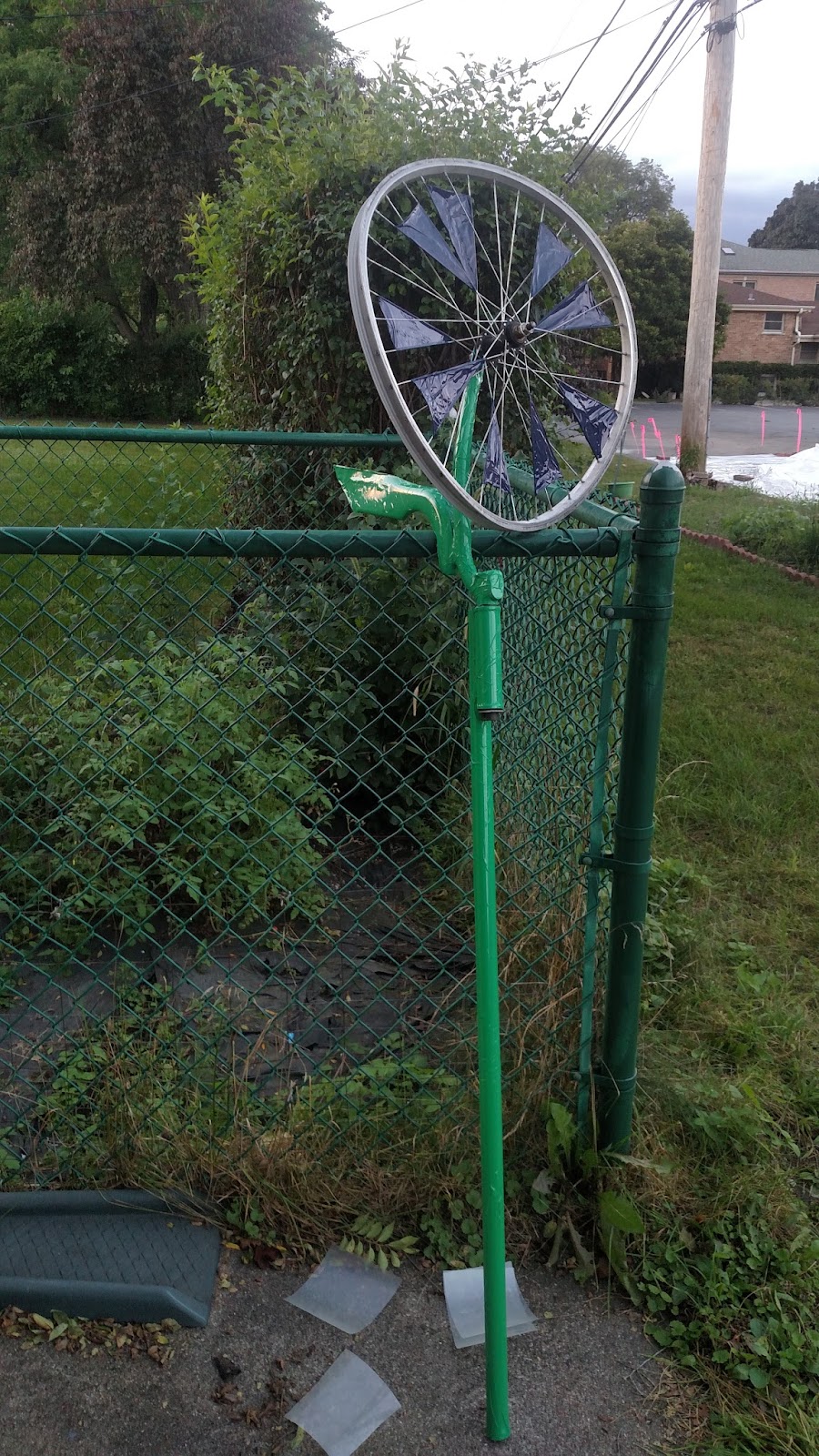
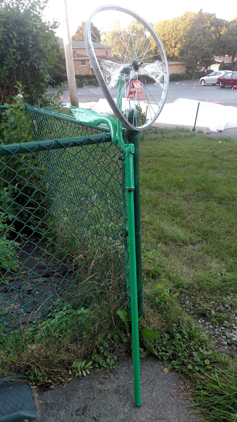
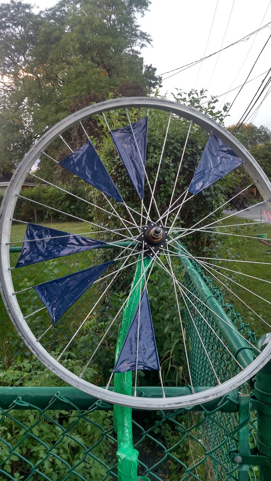
Build was successful in that it rotates smoothly in the x and y and is visually playful. I like how the bicycle parts look covered in vinyl. The "flower" stem and face came out as envisioned
rolling resistance was adequately low but could be lowered further. I think I want to build some wheel having investigated this topic as part of the project and as a commuter cyclist who always wants to go faster.
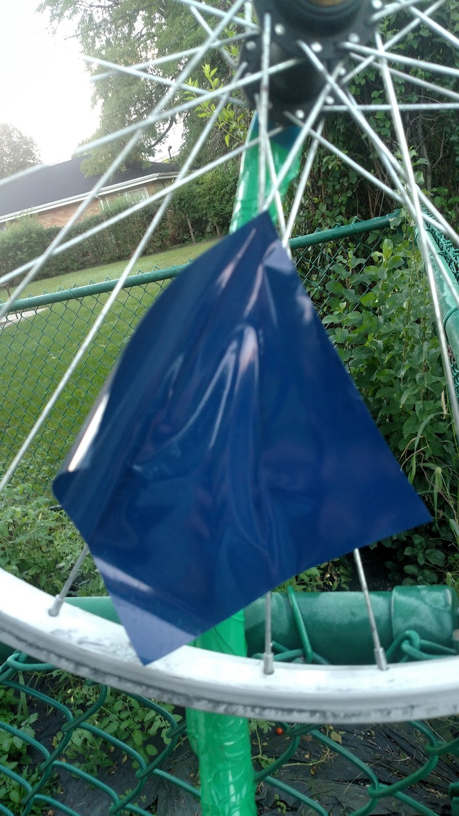
I need to rethink blades to better capture wind. The vinyl on spokes approach is better than the saran wrap I tried but hardly a resounding success. Comments bellow on other approaches would be appreciated. Current improvement that occurs to me is tacking pre cut blades sheet metal to the spokes.
The weld fit up /tacking was challenging. If I were to repeat might jig. Might notch where I cut off fork tine to improve fit.
Finish of vinyl was good but could have been perhaps better. I had never applied vinyl before and getting it to stick to curved/uneven surfaces was very challenging. I didn’t mind that there was some cracking/bubble lines but probably not the cleanest aesthetic. Might sandblast and powder coat next time to create a more even finish.
Overall was fun and interesting getting used parts and turning into a budding piece of sculpture for a new sculpture artist. Hope you enjoyed!
rolling resistance was adequately low but could be lowered further. I think I want to build some wheel having investigated this topic as part of the project and as a commuter cyclist who always wants to go faster.
I need to rethink blades to better capture wind. The vinyl on spokes approach is better than the saran wrap I tried but hardly a resounding success. Comments bellow on other approaches would be appreciated. Current improvement that occurs to me is tacking pre cut blades sheet metal to the spokes.
The weld fit up /tacking was challenging. If I were to repeat might jig. Might notch where I cut off fork tine to improve fit.
Finish of vinyl was good but could have been perhaps better. I had never applied vinyl before and getting it to stick to curved/uneven surfaces was very challenging. I didn’t mind that there was some cracking/bubble lines but probably not the cleanest aesthetic. Might sandblast and powder coat next time to create a more even finish.
Overall was fun and interesting getting used parts and turning into a budding piece of sculpture for a new sculpture artist. Hope you enjoyed!
Up-Cycled Weather Vane: Pt. 2
Build was originally envisioned with sketches and dimensions. I based the height off of sculptures I had seen in the sculpture park on Mccormick ave in Skokie IL.
Parts were cut and fit was adequate so that parts could be welded square to each other.
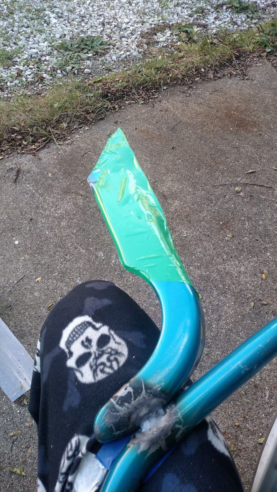
Testing of functionality for spinning of wheel and of fork so it could move freely with wind. I used a box fan to test ease of spin. This testing led to additional functionality of leaf tail to fork.


This leaf was added so as to be more stable in wind (built from tin snipped half of the bicycle chain guard). Bearings were swapped to lower rolling resistance. I am glad the frame I used was a very solid steel Schwinn frame as the gauge of the walls on all of the parts was nice and heavy limiting heat warp and allowing for beefy welds.
*fun fact Chicago was once known as the bicycle capital of the world in part because of the manufacture of Schwinn bicycles in the city*
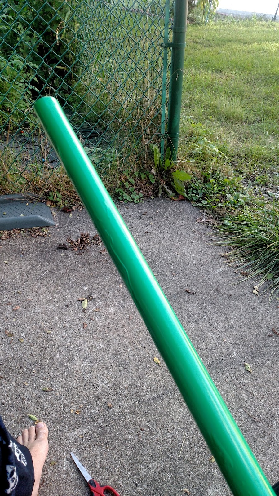
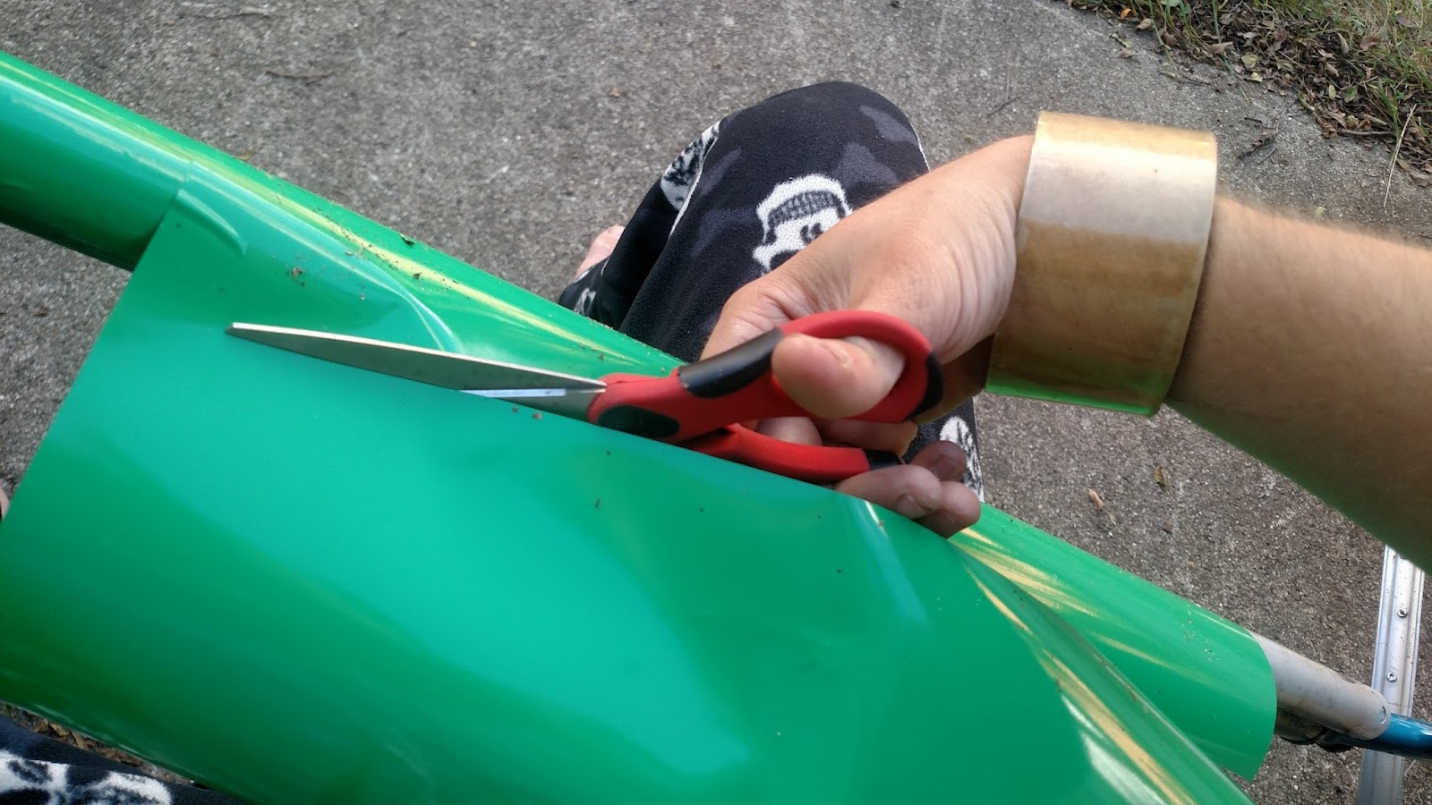
Finish was determined and installed (green vinyl with blue accents to give a flower like appearance of (I like forget me nots and will likely color the hub yellow in the future). The green vinyl was a fun pickup. I thought about going with something more natural but decided for a more distinct color combination. I initially tried to use saran wrap for the blades on the spokes but then went with sections of vinyl. I applied all of the vinyl in sections to make it easier to apply. This was much less time consuming than painting. All parts had been previously cleaned for welding so prep was fairly minimal except for cleaning the welds and heat affected zone/additional spatter.


Possible improvements to wind blades/petals in future to improve wind capture. Perhaps swap hub and steerer tube bearings in future.Site of install to be determined.
Parts were cut and fit was adequate so that parts could be welded square to each other.
Testing of functionality for spinning of wheel and of fork so it could move freely with wind. I used a box fan to test ease of spin. This testing led to additional functionality of leaf tail to fork.
This leaf was added so as to be more stable in wind (built from tin snipped half of the bicycle chain guard). Bearings were swapped to lower rolling resistance. I am glad the frame I used was a very solid steel Schwinn frame as the gauge of the walls on all of the parts was nice and heavy limiting heat warp and allowing for beefy welds.
*fun fact Chicago was once known as the bicycle capital of the world in part because of the manufacture of Schwinn bicycles in the city*
Finish was determined and installed (green vinyl with blue accents to give a flower like appearance of (I like forget me nots and will likely color the hub yellow in the future). The green vinyl was a fun pickup. I thought about going with something more natural but decided for a more distinct color combination. I initially tried to use saran wrap for the blades on the spokes but then went with sections of vinyl. I applied all of the vinyl in sections to make it easier to apply. This was much less time consuming than painting. All parts had been previously cleaned for welding so prep was fairly minimal except for cleaning the welds and heat affected zone/additional spatter.
Possible improvements to wind blades/petals in future to improve wind capture. Perhaps swap hub and steerer tube bearings in future.Site of install to be determined.
Up-Cycled Weather Vane: Part 1
I chose dimensions based on the bicycle fork I used and wheel as well as a 4ish foot section of gray tube I had. I planned on this being a outdoor sculpture rather than a rooftop piece so I wanted something human height. The final build comes in around 6 ft.
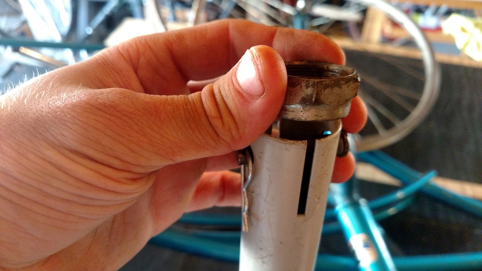
All of the parts being used was both a blessing and a curse. The wheel hub was in ok shape but the bearings were a bit pitted (nicked so as to no longer able to roll smooth). I hope to replace with ceramic bearings/races in the future both because they have low rolling resistance and because they are less susceptible to the elements. Rolling resistance for those who don’t know is the friction the bearings (little balls in the races (the holders that spin: https://en.wikipedia.org/wiki/Race_(bearing))) experience when rotating. Less rolling resistance means less force needed to move/spin the thing with bearings ( https://en.wikipedia.org/wiki/Rolling_resistance). Cyclists spend a lot of money on reducing rolling resistance. Getting awesome bearings with low rolling resistance is one of the easiest ways of buying speed for a racing bike.
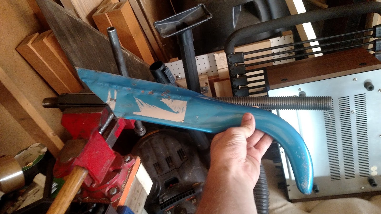
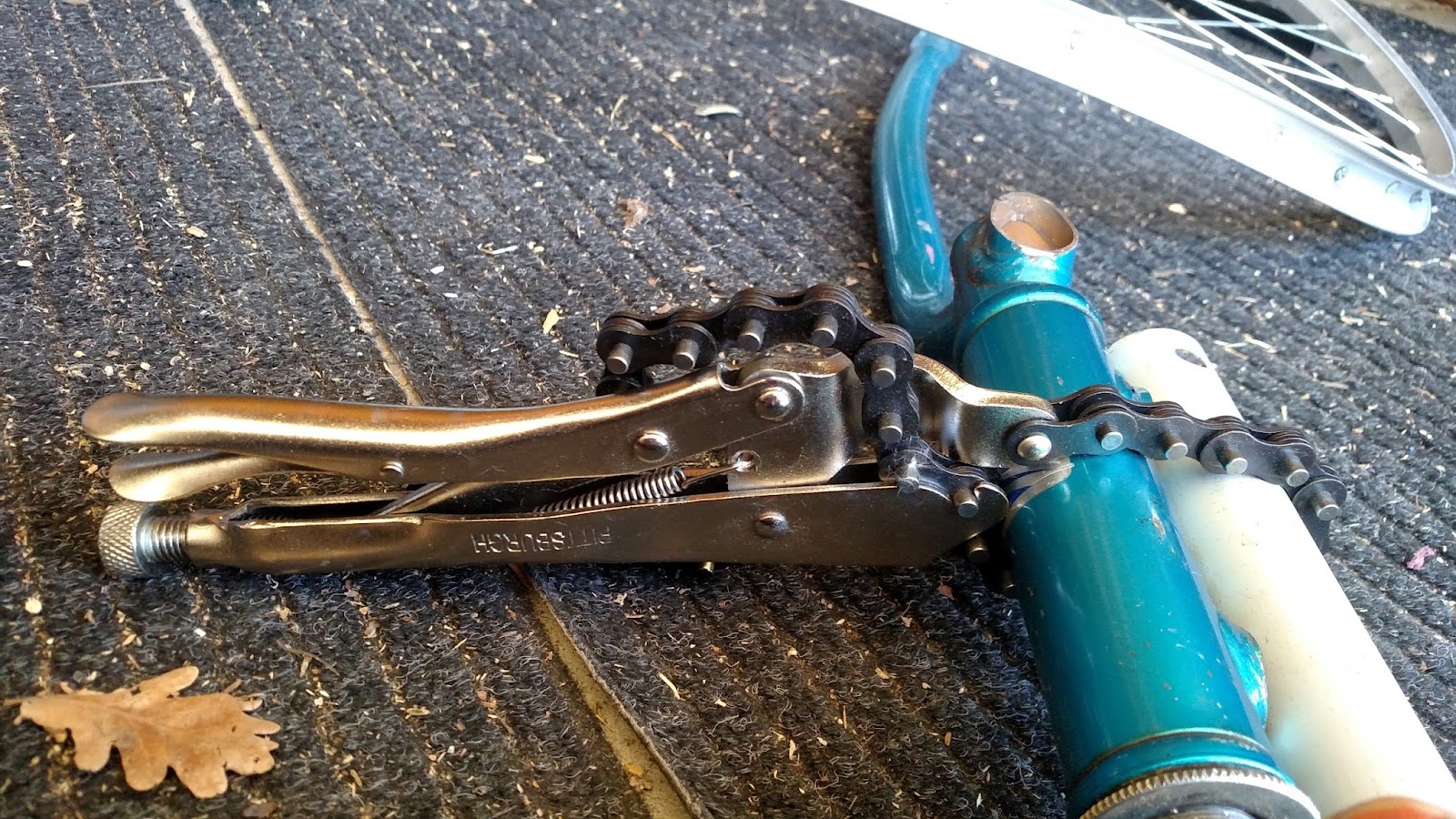
Build initially was cutting and fitting the bike fork pieces to the tube pieces. I cut off one of the bike fork tines because it was impeding the spinning of the wheel.
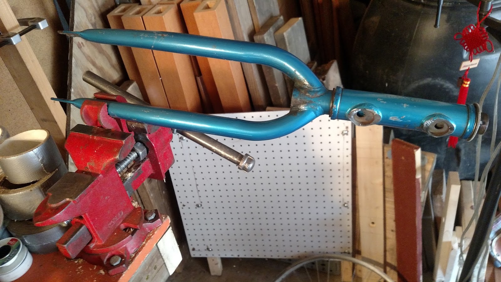

This was because the crashed wheel was very very out of tru (no longer consistently round). Initially I thought I would just weld the steerer tube to the long section of tube but this proved impossible as it would have impeded the rotation of the fork.
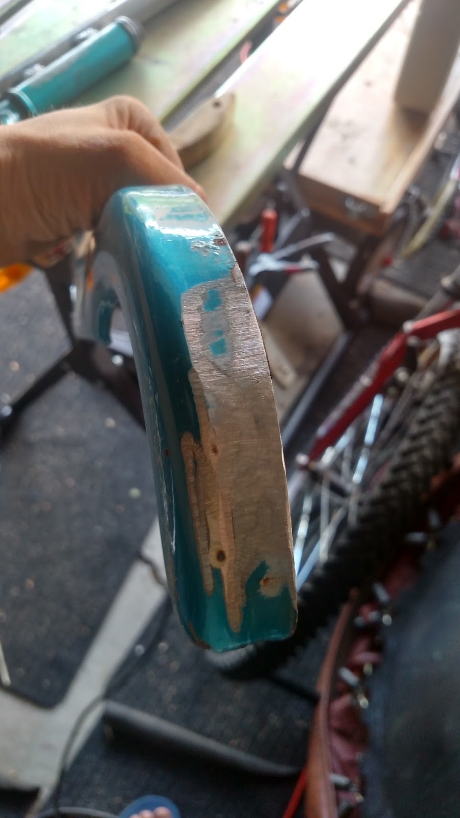
I then went with the second option of mounting to steerer tube face where the fork tine had attached. I grinded surfaces of fork /prepped for welding.
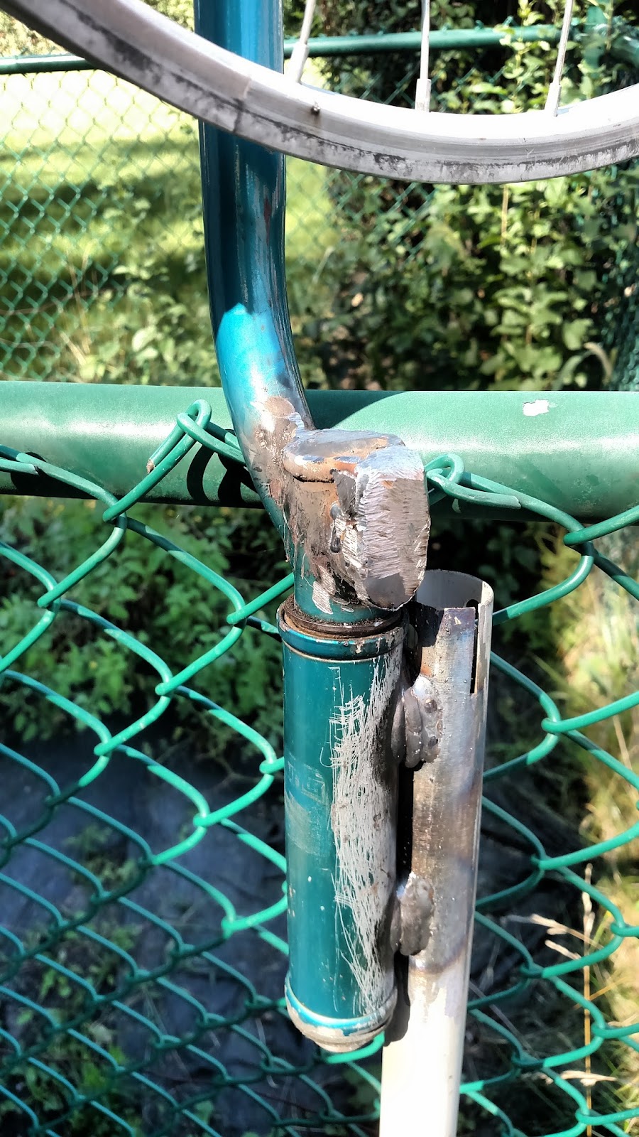
Initial fit up test showed that there was some overlap with moving parts so I ground down.
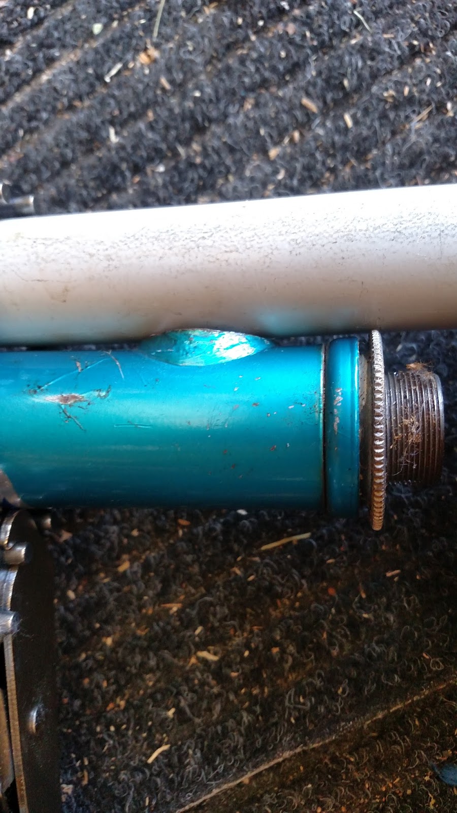
I then fitted scrap flat stock to seal openings so as to limit water getting into steerer tube and for aesthetic completeness. I mig welded the different elements after marking and clamping.
Welds were adequate but hardly structural. Mig welding can sometimes be used like a hot glue gun for metal. If you prep the two surfaces so there aren’t contaminants like paint and oil you can get things to join nicely with the heat/introduction of new metal.

As you can see the outer race is no longer gnarled.
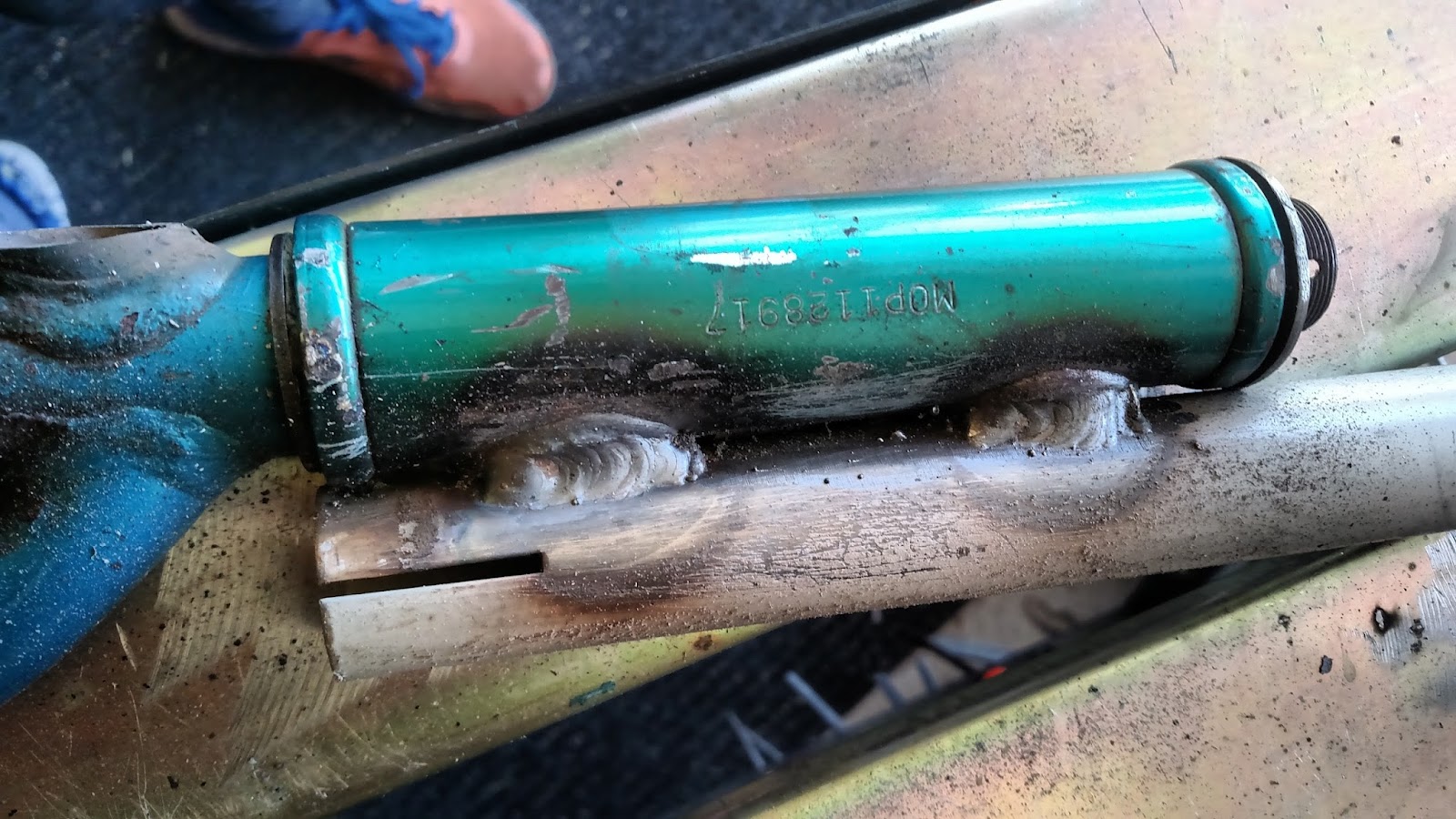
Welds had nice heat affected zones.
Afterwards I ground welds to create a more aesthetic appearance.

Up-Cycled Weather Vane: Introduction
Up-Cycled Weather Vane
My name is Joseph Prosnitz and I am undertaking a Weather Vane Build as a Bocca Bearings project
There is a long history of weather vanes as you can read about on wikipedia https://en.wikipedia.org/wiki/Weather_vane
*Fun fact they are often called weather cocks because they are in the shape of a rooster on top of churches.*
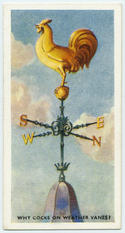
These wind measuring devices are both ornamental and indicate the general direction of wind. I have always liked that they catch the eye on a windy day. This will be my first build of one. I researched how they are traditionally constructed and discovered they are fairly simple. I decided to reuse a bicycle I had lying in the shop as it had been crashed. The greatest difficulties I foresee are the weight considerations as a vane that is too heavy won’t track the wind at low speeds. I hope to offset this by minimizing rolling resistance. More on this later.
My goals for this project :
1. build a weather vein
2. up-cycle a used bike
3. create a piece of outdoor art
4. experiment with bearings
Primary tools used:
angle grinder
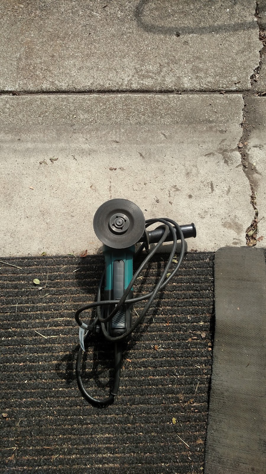
bench grinder

mig welder (you don’t need a spool gun like the one pictured)
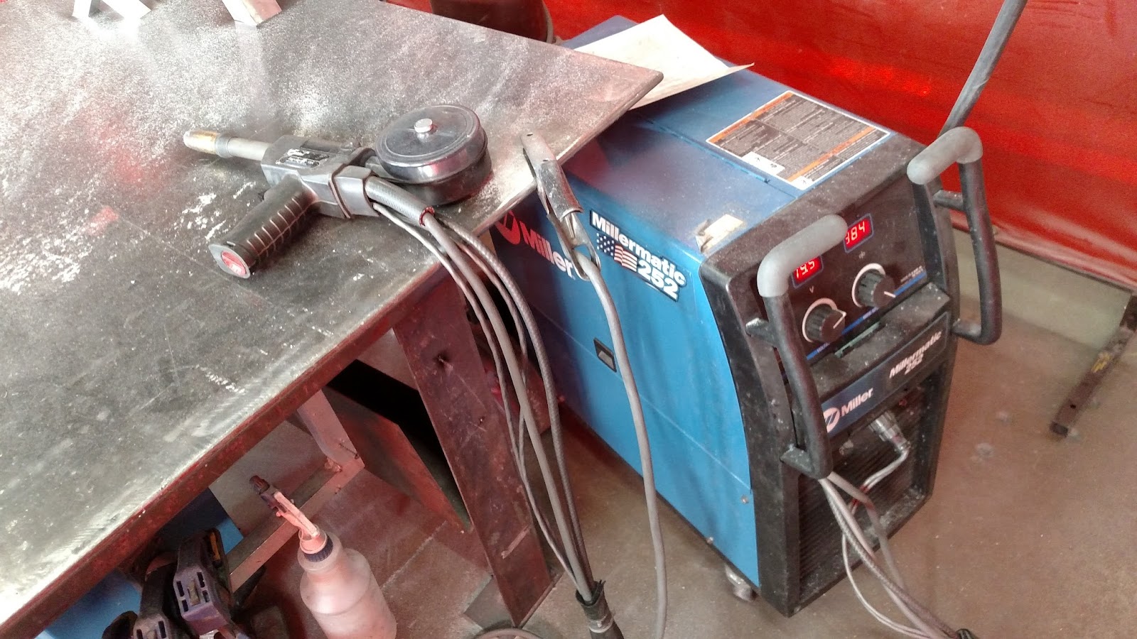
welding table
bench vice
Scissors
Parts:
used bicycle wheel
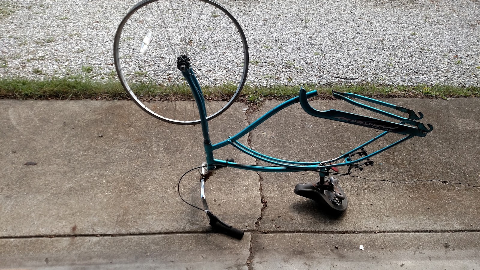
used bicycle fork
bicycle races
metal tube

Scrap metal
vinyl
Subscribe to:
Posts (Atom)