Scan-o-tron project: Building accessories


The Scanotron build is at full-steam. The Eureka Factory is currently building the project accessories.

The accessories in this case is the framework for the monitor that people will be able to watch the scanning on. The metal bars on each side slide onto a wooden support and are held in place with pins. 


The board across the top drops into the frame and can be adjusted for height, depending on where you're exhibiting. A monitor mount will be attached to the board, so you can easily attach the monitor. Cables will run through the 80/20 tubing.


Scan-o-tron Project Introduction

If you haven't heard of the Eureka Factory yet, you might not be paying attention. This is an incredible group of creative individuals and business partners who believe in the power of community-driven innovation to help people move from passive consumption to empowered and active creation. They have just recently organized Roboticon Tampa 2014, working hand-in-hand with FIRST to bring kids, teens, and parents together to work on, build, and compete with their robots.

Adding to their repertoire, the Eureka Factory has an ongoing major project. This project is called the "Hive", a 10,000 sq. ft. makerspace at John F. Germany Library in downtown Tampa that's having their grand opening on November 15th.


And now, they have rolled up their sleeves yet again to work on a very innovative project. In partnership with Boca Bearings, they have set out to construct The Scanotron!


Their build consists of an apparatus that will be able to scan a person's body, head to toe, 360 degrees, and transforms it into code compatible with a 3D-printer.


In short, that means that a person could potentially scan their own body then print a miniature version of his/herself!


Seriously, how cool do you have to be to have an action figure of yourself? We will be updating this blog as we go, so keep an eye on things here or on our social channels. 


"The Crossfire" 3D printed quadcopter - Part 6 - The 3D Printer Saga

Well, we've had to take a bit of a detour over the past few weeks to get our 3D printer working again after the extruder failed. Since this blog is to document the entire process, including all the pitfalls along the way and all the things we learned, here is how we worked through it.

For whatever reason, we had 2 components on our 3D printer fail at or around the same time. The first was the RUMBA board, which is what controls the stepper motors that drive the X, Y and Z axes as well as the extruder. The second was the hot end, which stopped heating up due to a failed resistor.

The first thing I dealt with was the RUMBA board. Our printer is under warranty, so they sent us a new board, and it was a relatively easy switch. There are quite a few connections to the RUMBA, so I took a picture before removing the old one.

Replacement RUMBA board before install. Not that the new board does not come with motor drivers, of which there are 4. (one for each motor) They are easy to remove and plug right into the new RUMBA


Once we got the X/Y/Z motion working again, it was on to the problem of the extruder nozzle (known as the "hot end") not heating up. I wasn't sure if the problem was the hot end itself, or some other problem. The temperature sensor was working, and was showing the correct temperature. I unplugged the heater leads and confirmed that there was voltage going to the hot end, so that had to be the problem.

Multimeter showing 14.5 volts going to the hot end

Since now I know where the problem lies, I had to figure out how these extruders work, being that this is all new to me. It turns out they are very simple devices. A hollow nozzle made of brass, with a milled aluminum block to conduct heat, and a 6.8 ohm resistor that does the actual heating. A 100k ohm thermistor provides the temperature measurement. It's all held together with some sort of high temperature putty and kapton tape.

The "J-style" hot end used in the Type A Machines series 1. The green resistor is what failed, it normally sits in the groove in the aluminum block, heating up the brass components and melting the filament.

Measuring the current across the resistor revealed that no current was passing through, so there was the problem. I did a bit of research, and found out that the resistor used is this one right here:

http://www.newark.com/vishay-sfernice/rwm04106r80jr15e1/resistor-wirewound-6-8-ohm-3w/dp/73M8369

6.8 ohms, 3W, They were cents apiece. We bought 10. A few other things we bought were some high temperature wire, PTFE insulation, and some new connectors. I chose not to try to salvage the old connectors or wiring, since it was quite easy to reconstruct that whole setup. Keep in mind when working with these, that everything needs to withstand some pretty high temperature. The putty that used was muffler putty used on car exhaust systems, it's good up to 500ยบ C


Re-assembled hot end ready for testing

3D Printer interface with temperature graph, showing that everything is working as it should.

Once we got the printer working again, I struggled quite a bit with my prints warping. I tried printing at different speeds and temperatures, but I still got quite a bit of warping on these drone arms. For now I am printing the last 2 arms in white filament, since that seems to perform better than any other color that we have. The quality and properties of your filament have a huge effect on how your prints come out.


So now that I've finally got the last 2 arms printed, I can go ahead with the final assembly of the drone.

Back to business!


I realize there isn't a whole lot of actual "drone" news to speak of in this entry, but this is all part of what it takes to get us where we want to go. But we are pretty much finished printing now, so we are getting very close to assembly and test flight.


"The Crossfire" 3D printed quadcopter - Part 5 - Power Distribution

Well, the our 3D printer is down right now. Luckily, I have plenty to work on until we get it fixed. It's a great time for some soldering.

To connect the motors to the ESCs, I used 3.5mm bullet connectors, with heat shrinks. Male connectors on the motors, females on the ESCs. With any power connections, always put the female end on the battery side (the side that power will be coming from) and male connectors on the side that is receiving power. This prevents shorting the battery accidentally.


To get power to all four ESCs, I chose to use an EC5 connectors at the battery, split it four ways, and use EC3 connectors at each of the ESCs. To keep it simple, I soldered all 4 wires into a single EC5 connector, rather than use a power distribution board or start with 2 and then split 2 into 4.


Finished power harness
Electronic speed controls with female bullet connectors on the motor side, male EC3 connectors on the battery side.

I recommend getting a set of "helping hands" to help. You can buy them off the shelf at Radio Shack or order them cheaply from Amazon. It makes the whole process a lot easier.


If you're new to soldering, there are a lot of videos on YouTube to help get you up to speed. This one was helpful to me since EC3 connectors, EC5 connectors and bullet connectors are exactly the same when it comes to soldering, and it's a good, quick how-to on how to assemble the connectors:

https://www.youtube.com/watch?v=u8aF3-4uBkQ

Solder a few practice pieces to get familiar if you've never done it before.

I also highly recommend using heat shrink, I got mine at Home Depot for a few bucks per pack.

I don't have a heat gun at home. To shrink the heat shrink, I got this little Bernz-O-Matic butane torch for $9.99 from Home Depot which has a heat gun tip, and also a soldering tip. I haven't tried the soldering tip yet, but I think it's great to have a cordless soldering iron if I need one.

I cut small pieces of heat shrink, put them over the connectors and hit them with the torch, it makes a nice,clean-looking connection that won't short.

Even though the 3D printer is down, I have printed enough various quadcopter pieces that I can make a basic mock-up of the quad using what I do have. In fact, everything but the 2 blue arms will probably be used in the final build. The blue arms were test prints that ultimately won't be used. I attached the ESCs to the arms with velcro strips and plugged them into the power harness. The next steps will be that I mount the motors, and connect the radio and flight controller so I can start testing all that stuff.

Rough mock-up with ESCs

"The Crossfire" 3D printed quadcopter - Part 4 - Sketching & Printing

One of the things that came up with my test print, was that the screw holes on the ends of the arms did not match up with the screw holes on the motors I got.

Not to worry, though. The designer has provided the SketchUp files for all the parts on the quad, so that adjustments to the files can be made. SketchUp is a free, easy to use design program.

http://www.sketchup.com/

If you've never used it before, there are some great tutorial videos to help you get started...

http://www.sketchup.com/learn

 I loaded the the arm into SketchUp and moved the holes around to where I needed them. To see whether or not I had them in the right place, I didn't want to print an entire arm, so I took just the surface with the screw holes in it, copied it to a separate file, made it 2mm thick and printed a small disk that I could test with my motors. It's a good thing I did that, I printed about 4 of these disks before I finally got it right. The screw holes positions in the motors are not exactly uniform, and I ended up making the holes slightly oval shaped.


I also went ahead a printed a new bottom plate, since the white PLA that we have is really good quality.


Now that the bottom plate is done, I've got a print going of a top plate that has the screw holes in the right position for the KK2 flight controller.


This is the file I used for the top plate, since it was the only top plate I found that seems like it won;t give me problems when I try to mount my flight controller: http://www.thingiverse.com/thing:151821

I'm going to keep on printing parts, keeping the printer going almost non-stop. We are supposed to get some new PLA colors in tomorrow, so I'll most likely be able to  start printing the arms, which I plan to do in black. I also got some hardware in to test the electronics. (servo cables, EC5 connectors, etc)

Stay tuned.

"The Crossfire" 3D printed quadcopter - Part 3 - Understanding the Radio

While I am waiting for the last of the components I need, one thing I can do now is learn how the radio works. This is my first time working with a programmable multi-channel radio/receiver setup like this, so I'll need to educate myself on binding and programming it.

After throwing some batteries (8 AA) into the radio and turning it on, so far so good.


The next stop is to bind the receiver to the transmitter. The radio comes with a corresponding receiver which goes into the quad (or whatever you are using it for) to receive the signals from the controller and send them to the flight controller. To "bind" them simply means to establish the link between them. A quick youtube search quickly yielded results.

The receiver comes with a "bind" plug, which is a loop that just jumps 2 pins together on the bind port of the receiver when plugged in.

Also you need to be able to get power to the receiver as well. The way a radio receiver is normally powered (the flight controller too, actually) is by receiving power from one of the four electronic speed controllers. (ESCs)

 This is where I had to improvise a bit, since I do not have the proper connectors yet to connect the quad battery. I do however, have a Traxxas Slash with a perfectly good battery and speed controller, so I decided to use that for the purposes of binding the radio and doing some experimentation. Using YouTube as a general guide, I plugged the ESC into channel 3 of the receiver, plugged the battery into the ESC, and powered on the ESC. The connectors are universal. Sure enough, the red light on the receiver began flashing, indicating it was ready to bind.

The actually bind procedure is incredibly simple. With the transmitter powered off, you hold down the bind button on the back of it, and switch on the transmitter. The transmitter beeps once, and the light goes solid indicating a successful binding. Easy peazy.

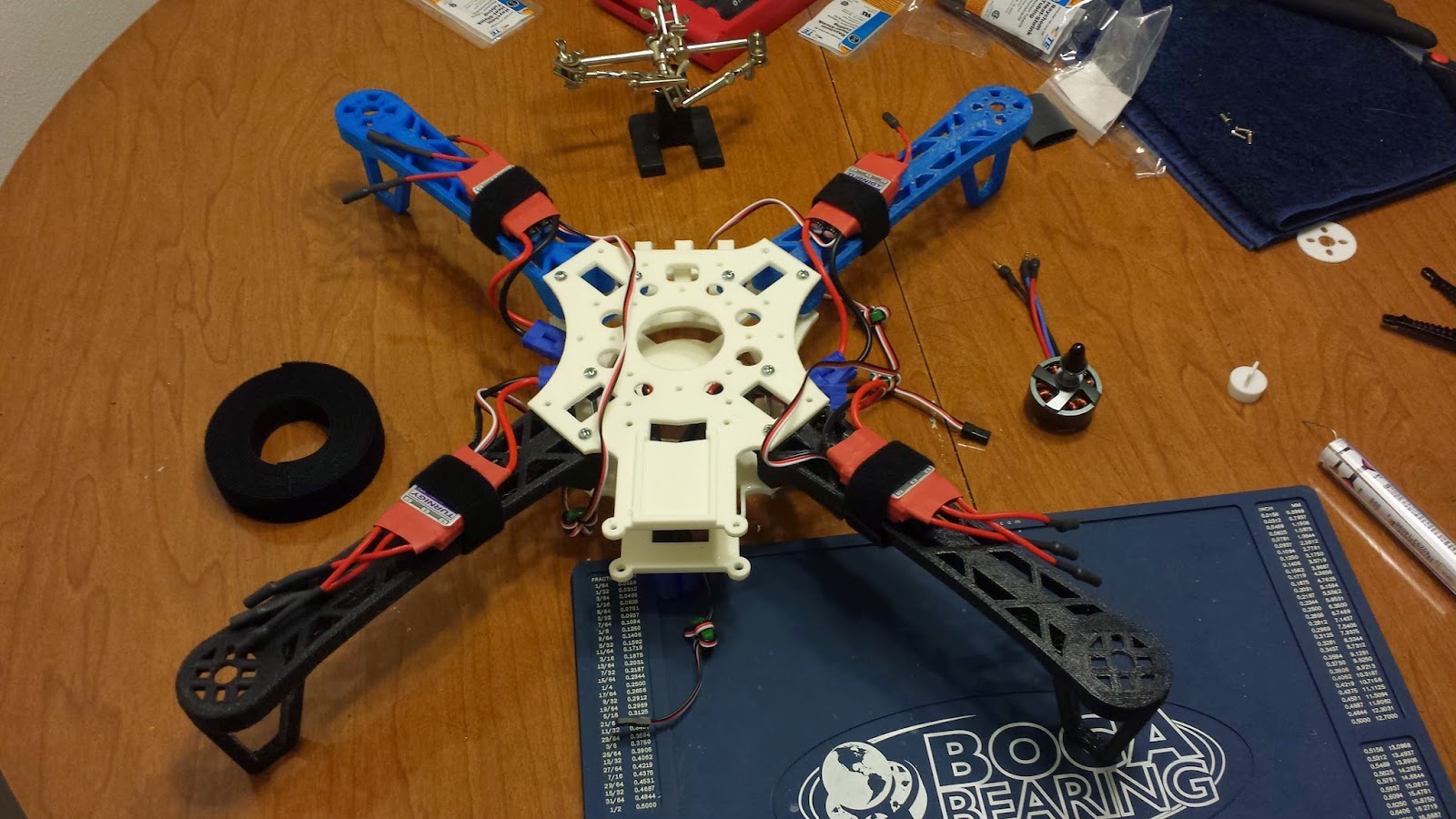
The setup I used to bind my transmitter.

Now that was in experimentation mode, I figured I would see if I could play around with this a bit, and see if I could actually control the steering or throttle of the car by using the outputs of the radio. After plugging the servo into a few of the channels and trying the controls, I got the steering to respond perfectly to the right control stick. The throttle was a bit tricky, and at one point, the throttle got stuck on maximum with the car on my kitchen table, the wheels landed on the entire 53 page manual for the radio that I had printed which flung paper everywhere, the cat took off and hid under the bed, and the whole thing ended with me holding up the car by the back bumper (like holding a shrieking possum by the tail) and disconnecting the battery with my other hand.

Eventually I got it set up to where I could even drive the car. I got the throttle set up on the left stick, with zero as the midpoint and then forward and reverse, and the steering on the right stick. It's cumbersome and really awkward to drive an RC car with an airplane controller, I wouldn't recommend it, but this is about experimentation and was a way for me to learn a few things about radio setup without having the quad ready. I even connected one of the flashing LEDs to the landing gear switch.


I didn't touch the throttle in this video because the car is sitting on the Boca Bearings conference room table, but it does work.

This radio has a ton of settings and adjustments you can make, so I recommend studying the manual and testing out some things for yourself.

A few things:

Here is the video I used to find out how to bind the Turnigy 9x - https://www.youtube.com/watch?v=zuJgfA3_Jqw

Links to the Turnigy9x manual:

Part 1 - http://www.hobbyking.com/hobbyking/store/uploads/529892926X11510X47.pdf
Part 2 - http://www.hobbyking.com/hobbyking/store/uploads/529892926X11510X33.pdf

Now I can more forward with my project confident that I have a working radio, and that I know a little something about how to use it.....

"The Crossfire" 3D printed quadcopter - Part 2 - The Electronics

Now that we're confident in our ability to print a solid frame that would work well, it's time to order the electronics. We used Hobbyking to source our parts, despite the notoriously slow shipping, since they had pretty much everything we needed at very reasonable prices. We aren't in a big hurry with this project anyway, it's about learning and having fun creating something.

The designer of this quad gives a list of suggested electronics which I used as a guide.

Our parts list is as follows:

Four AX-2810Q 750Kv Brushless Quadcopter Motors   -  $20.85 each

Three pairs of 10x5E carbon fiber props - $8.05 per pair

(the motors on a quadcopter spin in opposite directions to balance out torque. Two of them spin clockwise, 2 counterclockwise. This is why props come in pairs when you buy them, one spins one way, and one the other way. We bought a third pair to have an extra set just in case)

Four Turnigy Plush 40 amp electronic speed controllers - $22.20 each

(Speed controllers vary the amount of current sent to the motors, based on signals received from the flight controller)

Hobbyking KK2 1.5 flight control board with LCD - $29.99

(The "brain" of the quad. This will accept signals from the radio and drive the motors accordingly.)


KK2 flight controller
Turnigy nano-tech 4000mh 3 cell LiPo battery - $33.70

Turnigy 9x 9 channel transmitter with 8 channel receiver for controlling the quad - $69.97

On board LiPo low voltage alarm - $2.17

Four Hobbyking cool looking blue flashing strobes - $3.42 each

Electronics total = $384.52


All I need now to start really getting things together is a few minor (but crucial) items like connectors to build the wiring harness, some basic hardware to hold everything together, and of course to re-print the frame. I hope to pick up the parts locally this weekend. And at least crank out a few frame parts over the next day or two.

Stay tuned....

"The Crossfire" 3D printed quadcopter - Part 1

The Crossfire
Hey Guys!

I'm very excited to show you our current project at the Boca Bearing's Workshop. We recently purchased a Type A Machine 3D printer. We figured, we already have a GoPro, we had a lot of fun with the AR Parrot Drone 2.0 that we've been flying around the warehouse.

We think we're ready to step up our game and start working on a full sized multi-rotor that will allow us to take some outdoor aerial video. More importantly, we want to really use this project to learn about 3D printing, electronics, and what goes into making your own functional radio controlled item. That and it'll be great to get out and get some fresh air once in a while. 
Goal:
To build a quadcopter using a 3D printed frame and off the shelf electronics.

Design
The design we've chosen to go with is the Crossfire
http://www.thingiverse.com/thing:32281

The is what a finished version version of this quad looks like.
Credit to MikeyB for the photo and for this design.

We're printing it in PLA plastic on a Type-A machines Series 1 3D printer. The first iteration came out slightly warped, and had a few other issues, but it's a good proof of concept. These parts were some of the first attempted prints we did when we were still learning how to use the printer. Our prints improved quite a bit since then, the next one we print will (hopefully) be the one we ultimately use for the build.

Our first 3D printed quadcopter frame

This is my first build of this type. I'll be using this blog to document our progress, the learning process and all the pitfalls we encounter along the way.